Weider 831.159360 Manuel d'utilisateur
Naviguer en ligne ou télécharger Manuel d'utilisateur pour Sports et loisirs Weider 831.159360. Weider 831.159360 User Manual Manuel d'utilisatio
- Page / 29
- Table des matières
- MARQUE LIVRES
Résumé du contenu
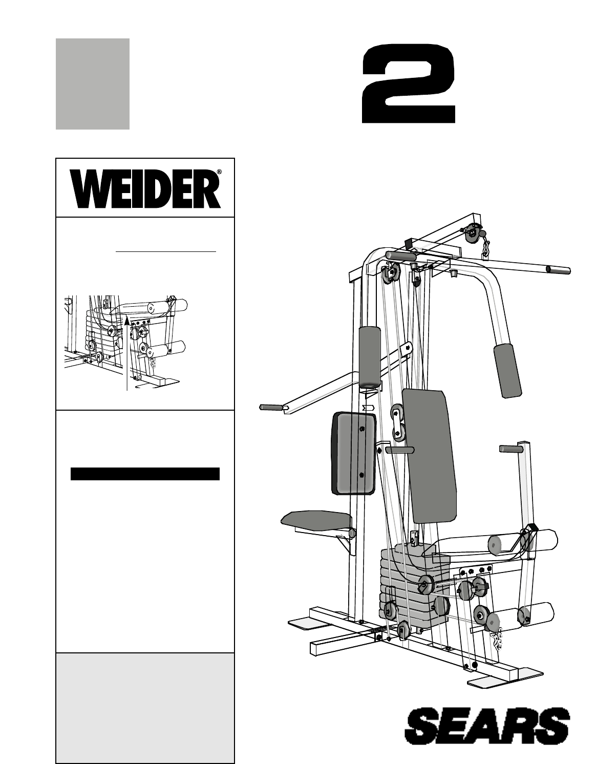
PATENT PENDINGTMModel No. 831.159360Serial No.The serial number can be found in thelocation shown below. Write the serialnumber in the space above.CAU
1018. Route the Medium Cable (23) around the “V”-Pulley (6) on the Right Arm (48). Be surethat the Cable is in the groove of the “V”-Pulley and that t
1121. Wrap the Medium Cable (23) around a 3 1/2”Pulley (15). Attach the Pulley to the TopFrame (55) with a 3/8” x 1 3/4” Bolt (87) and a3/8” Nylon Loc
25. Attach the end of the Short Cable (58) to theLong “U”-Bracket (57) with a 1/4” Nylon Lock-nut (2) and a 1/4” Flat Washer (10). Do notcompletely ti
1327. Locate the Long Cable (86). Route the LongCable under the 3 1/2” Low Pulley (88). Besure that the end of the Cable with the ballis on the indica
1431. Wrap the Long Cable (86) around a 3 1/2”Pulley (15). Attach the Pulley and a CableTrap (66) to the Press Frame (17) with a 3/8”x 3 1/2” Bolt (16
1535. Route the Long Cable (86) around the indicat-ed 3 1/2” Pulley (15) and through the Long“U”-Bracket (57). The Cable must bebetween the Cable Trap
1638. Press a 1 3/4” Square Inner Cap (44) into theRear Seat Frame (77).Insert the 1/4” x 2 1/2” Carriage Bolt (91) intothe center hole in a Seat Plat
1741. Press a 1 1/2” Square Inner Cap (32) into theFront Seat Frame (36).Insert the 1/4” x 2 1/4” Carriage Bolt (38) intothe center hole in a Seat Pla
1844. Press 3/4” Round Inner Caps (34) into theends of both Pad Tubes (28).Insert one Pad Tube (28) into the Front SeatFrame (36). Slide a Foam Pad (3
19ADJUSTMENTThe instructions below describe how each part of the home gym system can be adjusted. Refer to the exerciseposter accompanying this manual
2TABLE OF CONTENTSIMPORTANT PRECAUTIONS . . . . . . . . . . . . . . . . . . . . . . . . . . . . . . . . . . . . . . . . . . . . . . . . . . . . . . .
20ATTACHING THE LEG LEVER TO THE LOW PUL-LEY STATIONTo use the Leg Lever (29), the seat must be attachedto the front upright (see ATTACHING AND REM
21WEIGHT RESISTANCE CHARTThis chart shows the approximate weight resistance at each station. “Top” refers to the 6.5 lb. top weight. Theother numbers
22TROUBLE-SHOOTING AND MAINTENANCE Inspect and tighten all parts each time you use the home gym system. Replace any worn parts immediately. Thehome gy
234327788625432Base—1061—Low Pulley1—High PulleyLong Cable (86) Medium Cable (23) Rear Upright—19—Weight Stack9Short Cable (58)5CABLE DIAGRAMThe cable
1" Round Inner Cap (49)–61" Round Cover Cap (70)–43/4" Round Inner Cap (34)–45/16" x 2" Eyebolt (35)—11 1/2" Square Inne
1/4" Flat Washer (10)–105/16" Flat Washer (8)–113/8" Flat Washer (9)–71/4" x 2 1/2" Screw (43)–43/8" Nylon Locknut (21)–
1" Retainer (69)–45/16" x 1 3/4" Bolt (72)–11/2" x 3/4" Spacer (61)–23/8" x 2" Bolt (12)–33/8" x 3 1/2" B
Note: “#” indicates a non-illustrated part. Specifications are subject to change without notice.PART LIST—Model No. 831.159360 R0896AKey PartNo. No. Q
219157185211220156621152187805893271043237231021281811515211043413216507581027878191111127515111215661273321661257217166153936219859211566216534343030
Part No. 132823 R0896A Printed in Canada © 1996 Sears, Roebuck and Co.Model No. 831.159360QUESTIONS?If you find that:• you need help assembling orop
3BEFORE YOU BEGINASSEMBLED DIMENSIONS:Height: 76 in.Width: 38 in.Length: 59 in.Low Pulley StationFoot PlateHigh Pulley StationLat BarLeg LeverButterfl
4ASSEMBLY122711111578783551511141Before beginning assembly, carefully read thefollowing information and instructions:• Place all parts of the home gym
53. Press a 2” Square Inner Cap (27) into theRear Upright (56).Attach a Rubber Bumper (90) to the RearUpright (56) with a #8 x 1/2” Tap Screw (89).Sli
65. Set two Weight Bumpers (19) onto the bracketon the Stabilizer (5). Insert both Weight Guidesthrough the Weight Bumpers and the bracketon the Stabi
78. Attach the upper ends of the Weight Guides(62) to the Top Frame (55) with the 5/16” x 6”Bolt (60), two 1/2” x 3/4” Spacers (61), and a5/16” Nylon
812. Lubricate both axles on the Top Frame (55).Slide the Right Arm (48) onto the right axle.Note: Be careful not to confuse the RightArm with the Lef
914. During steps 15 through 36, refer to theCABLE DIAGRAM on page 23 of this manualto verify proper cable routing. Before begin-ning this section, id
Produits connexes et manuels pour Sports et loisirs Weider 831.159360
 (15 pages)
© 2020, manymanuals.fr. Tous droits réservés | 2.728 s |
 Manymanuals.com
 Manymanuals.de
 Manymanuals.fr
 Manymanuals.it
 Manymanuals.pl
 Manymanuals.cz
 Manymanuals.es
 Manymanuals-pt.com
Commentaires sur ces manuels